
|
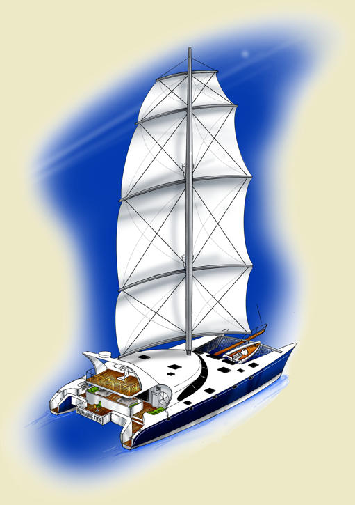
I now want to present one of those future designs! SQUARE-SAIL,
DynaRig: The DynaRig is a modern version of a 'square-rigger', but here the yards (yardarms/horizontal spars) do not swing around the fixed mast, but rather are attached permanently to the mast which is allowed to rotate to engage the wind angles. This requirement for a rotating mast precludes the old traditional staying of the mast, and results in a 'free-standing design'. Only recent developments in very hi-tech materials such as carbon fiber have permitted this DynaRig technology to be become reality. The German research had determined the optimum arc for the square-rigger's yardarms & sails to be effective pointing to windward. This 12.5-degree arc was reconfirmed by the Maltese Falcon design team. Much like the old square-rigs the total sail area on one mast is divided into rectangular panel sections 'stacked' on top of one another. Even the old names designating the different sails have been retained; the Courses on the bottom, then the Topsails, the Gallants, and finally the Royals. The individual rectangular panels can be sized proportionately to account for the desired sail area to be deployed for various wind conditions. Naturally the upper sails that can exert more overturning forces are smaller in size. I've chosen to make the 'courses' smaller than the 'gallants' for storm purposes. But I kept the yardarms of the 3 lower sails all the same length for manufacturing reasons. **Very interestingly the overall profile of this sail plan almost perfectly matches that of the idealized semi-ellipital/parabolic planform shape. The lift/drag factors for this optimized shape are so much superior to those for the triangular sail-shapes of the Bermuda rig. Doyle Sailmakers was employed to test and build the sails for Maltese Falcon. They discovered that when angled efficiently the square sails suffer very low loading due to the very extensive 'square edge support' provided by the yardarms. "In 50 knots of wind no more than 900kg loading was measured, tiny compared with leech loads on far smaller 'conventional' rigs." So simple Dacron can be used to good effect, in fact only 4 oz cloth in most of MF's rig. Non-heeling multihull vessels (particularly catamarans) experience difficulties keeping an 'aerofoil-shape' or 'flying shape' to their sails in light-wind conditions. But with light-weight sail cloth stretched between horizontal yardarms, the flying shapes can be better maintained. Even in heavier conditions the flying shapes will remain almost constant. Reefing this DynaRig is done progressively from the top down. On Maltese Falcon it was found that the 'royals' themselves (those right at the top) accounted for 40% of the loads on the rig, and with those furled her angle of heel reduced dramatically. The overturning moments on our Dyna-rigged multihull should act accordingly. It might surprise you that the 'royals' on Maltese Falcon are constructed of remarkably light 2 oz Dacron, and are "effectively sacrificed in 80 knots of wind." In other words, it will allow 'blow-out protection' in microbursts and/or unseen severe squalls. Reefed all the way down leaves just the 'course' sails flying. It has a very low CE at this stage, and like all of the other reefed configurations, it remains a 'balanced' sail plan. The course sail still presents a sizable sail area for really heavy-air storm conditions. An ultimate storm trysail arrangement is contemplated where the luff of this sail would ride in a slotted track mounted onto the rear facing outside wall of the mast tube, and then sheeted to the boat. Coincidently there is the possibility of two 'crow's nests' on the upper yardarms whose visibility would depend upon the stage of reefing employed. That slotted track for the trysail could be complimented with another, and the pair could provide a guideway for an 'elevator ride' to the crow's nest(s) with the help of an electric winch. On Maltese Falcon the sails roller-furl into a cavity in the body of the mast. I believe there is a design variation that will avoid this very extra complication, while concurrently allowing for a sealed mast tube. Erratic, quick motions are very tough on a free-standing mast. Multihulls are particularly guilty of providing sharp, quick motions that are exacerbated the further from the motion center you are. To alleviate some of the extra loading on the support structure of the free-standing mast, there are some 'staying' possibilities envisioned. As the mast only needs to rotate thru 130 degrees for sailing purposes, it's very possible to utilize a full time 'fixed' backstay. More intriguing is 'special running backstay' that could ease loading on the base support, as well as bending in the mast section itself. A 'removable/detachable' forestay for heavy pitching conditions can also be accommodated, and this might well be capable of carrying a roller-furled reacher sail as well. (Special note: there are no backstays or rigging in the cockpit area to interfere with big game fishing)
This DynaRig mast does not exert big compression loads to its base, but it does require considerable bending and torque support. This is provided by the X-structure formed by the athwartships 'spaceframe' bulkhead, and the longitudinal 'backbone rib' nacelle/front-frame combination. The 'bury' of the mast is approx 7 feet…about a foot more than that deemed necessary by the free-standing Aero-rig manufacturers. The 'spaceframe' bulkhead is patterned after Shuttleworth's FEA research on an Aero-Rig catamaran design. Carbon rib-arches incorporated into the cabin top are also envisioned.
Full automation is anticipated, but expected to be quite a bit less complicated than that of Maltese Falcon. Single-handed sailing is a reality. The auto-winching associated with sail handling will be done electrically, and might require less hardware than on MF. The mast rotation gear is accessible and located in a big compartment at the front of the cabin/saloon structure. This rig in its 'bare' state still represents a lot of windage. In a storm, or at anchor, this sizable windage factor located forward of the CLR of the vessel could cause the bows to be pushed off the wind to some considerable degree. For this reason the 'radar arch' has been fashioned bigger than would seem necessary to act as a stabilizer at the rear. It's ironic that this arch is there at all, as I swore a long time ago I did not like these things! I've tried to keep the 'flybridge' control station's drag at a minimum by utilizing a 'podium type' console, and a simple canvas top cover.
*Maltese references
**Semi-elliptical/parabolic reference
A) Rim-Driven Propellers: Instead of propulsion blades being attached to a central hub and propeller shaft, they are rooted to the rotating inner rim of a circular nozzle type unit. The rim is electrically driven with a permanent magnet motor, where the motor windings are in the stator and where the rotor has a number of permanent magnets. The electric motor is an integral part of the 'propeller nozzle'. These units are cutting edge technology. First came the rim-driven thrusters, and very soon the rim-driven propulsers. There are lots of pluses to recommend this new technology:
B) Diesel-Electric Powerplants: The rim drive units are electrically driven, so they would require some portion of the latest technologies associated with the ever expanding 'diesel/electric propulsion' technologies:
C) Conventional Propeller Drive: For those clients concerned about the new diesel-electric technologies, there are several conventional propeller configurations:
HULL
SHAPES: I present two offerings here:
MISC ITEMS of note:
This
could be a real fuel-sipping machine requiring less fuel weight
to haul and propel around, or seek out in remote locations. Demonstrated
savings can reach 30-50%. Under sail she could make 18/20 kts…under power 18-25 kts. Range…unlimited. She could skim over depths as little as 4'. Explore those rivers, mangroves, coves, lagoons. Dive or fish the flats and the reefs from the Bahamas to the Pacific atolls. This could be the ultimate MotorSailer |
![]()
![]()